Capacitors
Capacitance is the ability (or capacity) to store charge. A device that stores charge is called a capacitor.
Practical capacitors are conductors separated by an insulator. The simplest type consists of two metal plates with an air gap between them.
the symbol for a capacitor is:
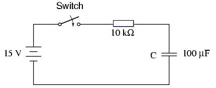
From the diagram below you can see that the circuit is open. The capacitor component provides a break in the circuit!
Why does current flow since the circuit is open?
The reason is that electrons are removed from the surface of one plate and pushed on to the surface of the other plate by the power supply.
The transfer of charge from one plate to the other allows current to flow until the potential difference across the plates is the same as the potential difference supplied by the power supply.
When a potential difference of 1 V is applied across a capacitor which stores 1 C of charge the capacitor is said to have a capacity of 1 Farad (F)
This is a very large amount of charge to store and so you will find that many capacitors are found to be in the range of mF, nF and pF. In any exam questions remember to look carefully at the prefix with the unit and apply the appropriate multiplier in your working and answer.
From the definition of 1 Farad we can see that the capacitance is equal to the charge divided by the potential difference. This leads to the following equation:
Example 1
A charge of 4 mC is stored on a capacitor with a potential difference of 2 V. What is the capacity of the capacitor?- Q = 4 mC = 4 x 10⁻³ C
- V = 2 V
- C = ?
C = 2 mF
Calculating the potential difference
Attempt to solve the question yourself before clicking the solve button!
Potential Difference and Charge
When we carry out an experiment with a constant current charging a capacitor it is possible to determine the realtionship between the potential difference supplied to the circuit and the charge stored on the capacitor.
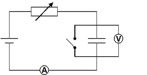
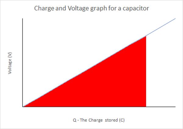
The results of this experiment show that the charge on a capacitor is directly proportional to the voltage and the graph we get is:
To determine the charge on the capacitor we use the relationship between current and time.
This is why we use a constant current circuit.
Example 2
When a constant current of 0.050 A is supplied to a capacitor for 10 seconds the voltage across the capacitor reads 45 V. What is the capacitance of the capacitor
- I = 0.050 A
- t = 10 s
- V = 45 V
- Q = ?
- C = ?
Q = 0.50 C
C = 0.011 F
Determining the capacitance
Attempt to solve the question yourself before clicking the solve button!
Energy Stored
The energy stored in a capacitor is equivalent to the area under the voltage/charge graph.
Since this is a triangle we can therefore see that the energy stored by a capacitor is:
Earlier you met the equation
Notice the difference in the case of the capacitor. Why is there less energy stored than when working with uniform electric fields and the work done by them? The key reason is that while the capacitor is charging the current is not a constant value and so there is, in effect, an averaging taking place which is given by the voltage/charge graph. Be careful in the exam to distinguish between the use of these two equations. The equation with the 1/2 term MUST be used when dealing with capacitors.
Knowing that E = 1/2 QV and that Q = CV we get:
Also we could substitute for V since V = Q/C. This results in the f0llowing relationship:
So the final equation can be written as:
Example 3
How much energy is stored in a fully charged 100 µF capacitor at a potential difference of 25 V?
- C = 100 µF = 100 × 10-6 F
- V = 25 V
- E ?
E = 3.1 × 10⁻² J
Example 4
A capacitor with a charge of 10.0 pF and a voltage of 50.0 V stores how much energy
- Q = 10.0 pF = 10 × 10-9 F
- V = 50.0 V
- E = ?
E = 2.50 × 10⁻⁷ J
Calculating energy stored from charge and capacitance
Attempt to solve the question yourself before clicking the solve button!
Calculating energy stored
Attempt to solve the question yourself before clicking the solve button!
Calculating potential difference across a capacitor
Attempt to solve the question yourself before clicking the solve button!
Charging a capacitor
When a capacitor is discharged there is 0 V across the capacitor and in an open circuit it will remain at 0 V. See the image below:
At the moment the switch is closed the only restriction to flow of charge is the resistor. We can use this to determine the initial current in the circuit.
Example 5
- V = 15 V
- R = 10 kΩ = 10 × 103 Ω
- I = ?
1.5 × 10⁻³ A
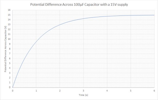
The current will begin to decrease as the capacitor begins to store charge. The stored charge on the capacitor will also generate an electric field which opposes the electric field of the supply. When graphing these changes the following graphs are produced:
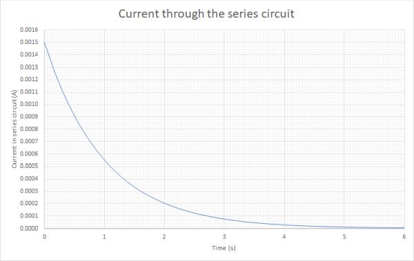
As you can see both the voltage and the current change over time. This is unlike the series circuits you have used before. Why does the current in the circuit decrease?
As the capacitor gains charge one plate becomes positively charged by the removal of electrons, and the other plate becomes negatively charged by the addition of electrons. This is done by work from the external supply. The electrons on the negative plate of the capacitor repel the addition of more electrons and so more work is required. It is also more difficult to remove electrons from the positive plate as the positive charge on the plate will attract electrons. The result is that the current gets smaller as time progresses.
Eventually when the electric field across the capacitor has a potential difference equal to the supply voltage no further current passes.
You can also see that the initial voltage across the capacitor is 0, but rapidly increases. The rate of increase slows down as the voltage across the capacitor approaches the supply voltage.
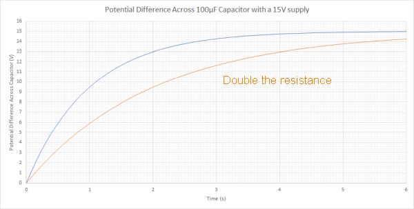
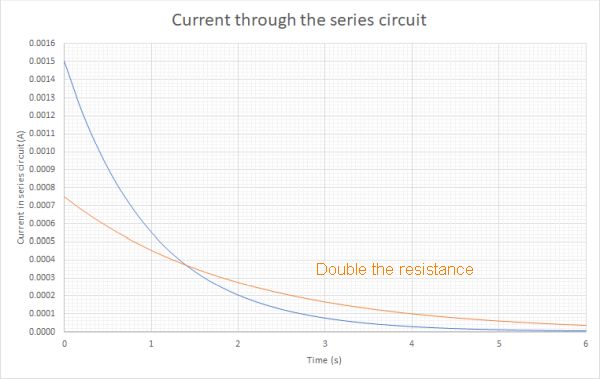
When we change the resistance and increase its value the curves remain similar in shape, but the rate of charging is slower because there is a lower current due to the higher resistance of the resistor. Below are graphs for the same circuit used above where the value of the resistor has been increased to 20 kΩ from 10 kΩ
Key points to note about these graphs
On the Voltage graph the rate of change of potential difference is slower at all points, but still starts from 0 V on an uncharged capacitor. The final voltage will still be the same as the supply voltage, but just takes longer to achieve.
The current does not start in the same place. We have twice the resistance, so there is half the current initially. As you can see the rate of change of current is also much slower and it takes longer for the capacitor to be fully charged. This makes sense because a lower current will transfer less charge per second, and so the capacitor will take longer to receive its full charge.
It is important to remember these differences if you are aksed to sketch the charging or discharging graphs for a capacitor.
Discharging a Capacitor
When a capacitor discharges through a series circuit it sends the current in the opposite direction to the one it was charged in. Plotting graphs of the discharge voltage and discharge current over time for the 15V and 100 µF capacitor are shown below:
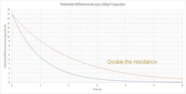
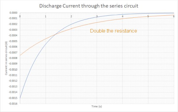
Key points to note about these graphs
The voltage for both discharges starts at 15 V, but the circuit with the higher resistor takes longer to discharge because there is a lower current depleting the charge on the capacitor.
Note that the current is flowing in the opposite direction to the supply and therefore the current graph starts at the max current in the opposite direction, hence it is below the horizontal axis. Again the initial current for the higher resistor has a smaller value than the lower resistor. The rate of change is also slower and so it takes longer to discharge in the higher resistance circuit.
Effects on Charging and Discharging a Capacitor
From the information above we can see that increasing the resistance in a series circuit slows down the rate at which a capacitor is charged. Therefore we can change the resistance in the circuit to get to pick a suitable time for the capacitor to charge or discharge.
What happens when we change the capacitance of the capacitor?
Increasing the capacitance of the capacitor will increase the time it takes to charge the capacitor. The capacitor is capable of storing more charge, but the current flow is initially determined by the resistor, and so increasing the capacitance means it will take longer for the capacitor to be fully charged.