Electrical sources and internal resistance
Electromotive Force (e.m.f.)
A source of energy in an electrical system such as a battery or a powerpack produces an electromotive force.
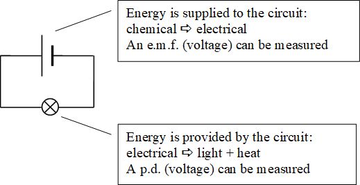
When energy is being transferred from an external source to the circuit, the voltage is referred to as an electromotive force (e.m.f.).
The emf is the amount of energy supplied to each coulomb of charge passing through it.
Sources of emf
| Source | Example |
|---|---|
| Chemical cell | Chemical energy drives the current (e.g. battery) |
| Thermocouple | Heat energy drives the current (e.g. temperature sensor in an oven) |
| Piezo-electric generator | Mechanical vibrations drive the current (e.g. acoustic guitar pickup) |
| Solar cell | Light energy drives the current (e.g. solar panels on a house) |
| Electromagnetic generator | Changes in magnetic field drive the current (e.g. power stations) |
Potential Difference
When energy is transformed into another form of energy by a component in the circuit, the voltage is referred to as a potential difference (p.d.).
Internal Resistance
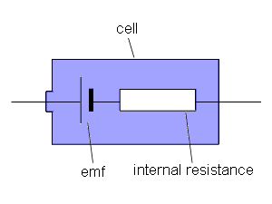
When a cell converts chemical energy into electrical energy the current must pass through the cell. The cell also acts as a resistor, and the resistance is referred to as internal resistance
As current is drawn from a cell the voltage measured by a voltmeter is lower than the emf of the cell. This is because some of the energy is lost pushing the current through the cell. The measured voltage across the cell is called the terminal potential difference.
The connection between tpd and emf is given in the equation
Where E = emf, V = tpd, r is the internal resistance and I is the current in the circuit
In an open circuit no current is drawn from the cell and so the t.p.d is equal to the emf.
The internal resistance of the power supply results in some of the energy produced in the power supply being used to push the current through the power supply. This energy is not available to the external circuit. It also depends on the amount of current passing through the power supply. The product of current through the power supply and its internal resistance is also known as the lost volts. This means that we can also write the above equation as:
Determining Internal Resistance
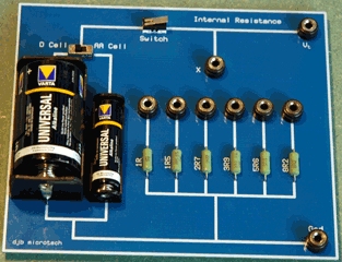
To determine the electromotive force of a non ideal supply and its internal resistance an experiment can be caried out with a series of resistors in series with the cell.
For each resistance the current and Vtpd can be measured. Plotting Vtpd against I willl produce a straight line graph with a negative slope. We can use three peices of data from the graph to give us the emf, the internal resistance and the short circuit voltage.
Let us rewrite the emf equation above into the form of a straight line (y = mx +c)
We want to have V as the subject of the equation.
or
A plot of V on the y-axis and I on the x-axis results in a graph where the gradient is -r and the Y intercept is the emf of the cell.
The line crosses the x-axis when there is the maximum current drawn, i.e. when the cell is short circuited. This tells us the maximum current that can be drawn from the cell.
Example 1
Use the graph to find the values of
(i) the emf of the cell
(ii) the internal resistance af the cell
(iii) and the current when it is short-circuited.
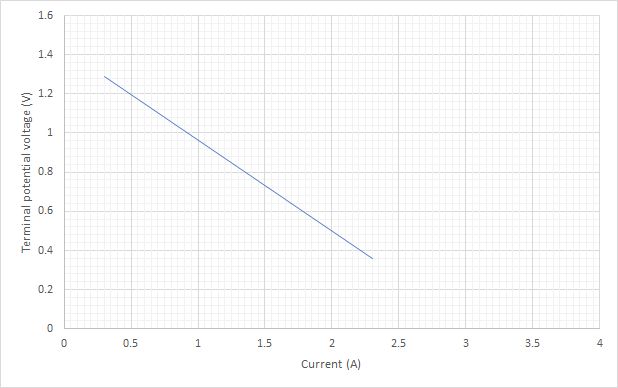
(i) To find the emf of the cell the line needs to be extended to cross the y-axis.
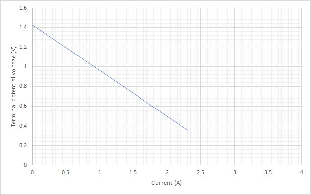
From this we can see that the emf of the cell is 1.43V.
(ii) The determination of the gradient gives us the internal resistance of the cell.
Choosing two points on the line far from each other
(0.4, 1.24) and (2.0, 0.5)
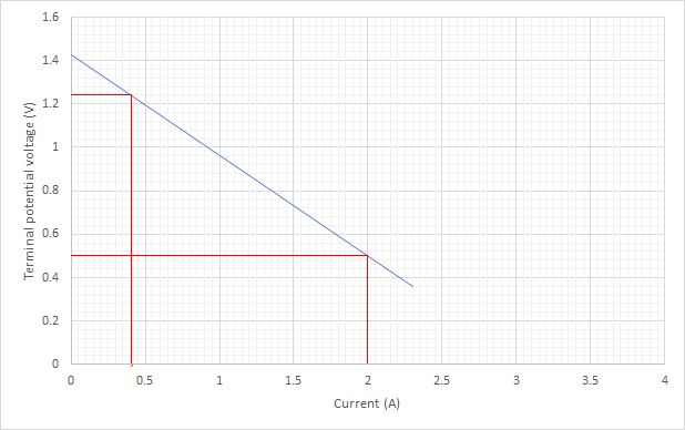
The gradient is equal to -r, the internal resistance.
Therefore the internal resistance is 0.46 Ω
(iii) The current when short circuited is given by point where the line crosses the x-axis.
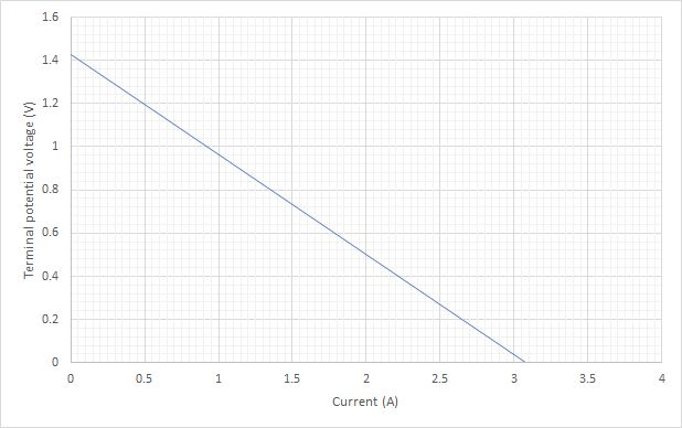
The value can be seen to 3.05 A.
Example 2
(a) A supply of e.m.f. 12.0V and internal resistance r is connected in a circuit as shown in the figure below.
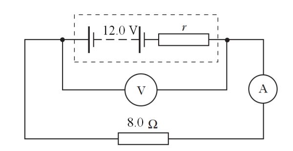
The meters display the following readings.
Reading on ammeter = 1.25 A
Reading on voltmeter = 11.50 V
(i) What is meant by an e.m.f. of 12.0 V?
(ii) Show that the internal resistance, r, of the supply is 1.6 Ω.
(i) The emf of 12.0 V tells us that the cell gives 12.0 J of energy to each coulomb of charge that passes through the cell. You could also say that it is the t.p.d. of the open circuit.
(ii) Using the equation
(b) A resistor R is connected to the circuit as shown below
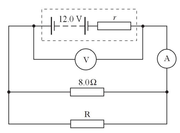
The meters now display the following readings.
Reading on ammeter = 2.0 A
Reading on voltmeter = 8.0 V
(i) Explain why the reading on the voltmeter has decreased.
(ii) Calculate the resistance of resistor R.
(i) The total resistance in the circuit has decreased because of adding the parallel branch. This results in a higher current flowing through the cell. The result of this is that the value of Ir (lost volts) increases.
(ii) The total resistance in the circuit is given by
RTotal = 4.0 Ω.
In a parallel circuit the resistances of the unknown resistor can be found by adding parallel resistors.
R2 = 8.0 Ω.
Internal resistance of a power supply
Attempt to solve the question yourself before clicking the solve button!
Interactive example 1 and solution
Attempt to solve the question yourself before clicking the solve button!