E
=
VIt
The electrical potential energy is provided by the power supply, which can be a powerpack, a dry cell, a battery, a generator or a solar cell.
REMEMBER charge carriers are not used up when transferring energy. They move back into the source and pick up more energy to transfer and then continue round the circuit.
Resistance
Ohm discovered that at a constant temperature the ratio V/I = a constant for most resistors. This is termed Ohm's Law and may be written in either of the two forms below:
Resistance is a measure of how much opposition there is to the flow of charge. It gives us an idea of how much energy will be used up when passing a unit of charge through the circuit.
Resistance is measured in ohms (Ω)
Electromotive force (e.m.f.)
The e.m.f. of a source is the electrical potential energy supplied to each coloumb of charge that passes through the source.
This is measured in JC-1 which is otherwise known as volts (V)
Power
Power is the rate at which work is done. Remember that P = E/t
From this the following details can be worked out:
Resistance in Series and Parallel circuits
Series
When looking at energy transfer in series circuits we know that the potential difference is divided by the components in series corresponding the ratio of their resistances. Think of adding an extra bulb to a series circuit and seeing how all the bulbs become less bright. We also know that the current is the same through all points of the series circuit.
Total Energy is equivalent to the sum of all the potential differences around the cicruit.
or
This can be further developed:
Since the current is the same at all points:
This shows that any additional component added to a series circuit will increase the total resistance in the circuit.
Parallel
In a parallel circuit when an additional bulb is added there is no change in brightness of either bulb. In other words the value of the voltage is the same at all points in a parallel circuit.
Since
Since the potential difference is the same at all points
Let us use this information to carry out some calculations. Look at the image below:
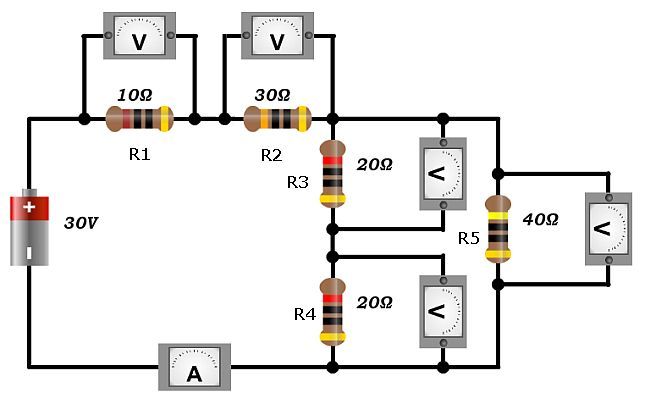
(a) calculate the current in the circuit.
(b) determine the potential difference across each of the resistors
Answer
(a) Let us calculate the resistance in the parallel part of the circuit (R3, R4 and R5).
Resitors R3 and R4 are in series, and can be added together to give the resistance for that branch of the circuit. This value can then be combined in parallel with the value from the R5 resistor.
Knowing the overall resistance in the circuit is 50 Ω it is now possible to determine the current in the main branch of the circuit.
(b) The potential differences across each resistor can now be calculated using Ohm's Law
V1 = 0.6 x 10 = 6V
V2 = 0.6 x 30 = 18V
The resistance of the parallel section is equal to 20 Ω therfore V5 = 0.6 x 20 = 12V
V3 and V4 are 6V each because they must add to give 12 V and are equal in resistance.
Resistors in Series or V1/V2 = R1/R2
In a series circuit the current is the same in all components. This means that a simple relationship can be expressed showing the relationship between the ratios of the potential differences across each of the resistors. This is given by:
If we know the potential difference across one resistor it is possible to determine the other potential difference by using the known value of both resistors.
What potential difference would there be across a resistor of 50 Ω when the other resistor with a resistance of 10 Ω in series has a potential drop of 8.0 V. We can use the relationship given above to find the answer. Let us state that V1 is the unknown potential difference. This makes R1 = 50 Ω, V2 = 8.0 V, and R2 = 10 Ω.
Substitute in the values to get:
As you can see above the choice of V1 as the unknown makes the calculation straightforward.
One way of simplifying the calculation is to make sure that the unknown piece of information, either potential difference or resistance is on the top line of the fraction. This means setting either V1 or R1 as the unknown peice of information and then filling in the other values that are given.
Determining an unknown resistance from two resistors in series
Attempt to solve the question yourself before clicking the solve button!
Potential Divider Circuits
Two resistors in series will divide the potential difference between them in the same ratio as their resistance.
Let us look at a typical setup:
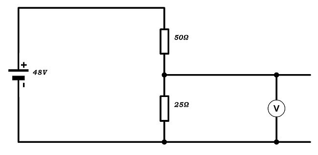
We can see that there are two resistors in series, R1 = 50 Ω and R2 = 25 Ω with a supply voltage, Vs of 48 V. Using the ratio of the resistances we can calculate the potential defference across R2 using the equation:
The potential difference across the other resistor must be the remaining potential
We can check if this works because the other relationship used with potential dividers is:
Which as we can see is true, therefore we have correctly calculated the potenital differences across both resistors.
Potential divider circuits are used in a wide variety of electrical circuits, including many control circuits with thermistors, light dependent resistors or potentiometers to vary the base voltage to an npn transistor.
Consider the following circuit, which uses a light dependent resistor to switch on a light emitting diode when the light level drops:
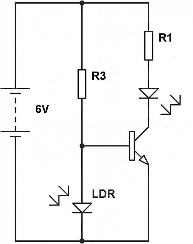
Looking at the circuit we can see that while there is light on the LDR it has a low resistance relative to the fixed resistor R3. This means that there is less than 0.7 V to the base of the resistor and the LED circuit is switched off.
As the light level drops the resistance of the LDR increases relative to the fixed resistor R3 resulting in a potential difference increase across the LDR. When the potential difference across the LDR increases to 0.7 V or above the transistor switches on the LED because there is now a high enough voltage to the transistor base.
It is therefore possible to see that the circuit can be used to switch on a light in low light level, and switch it off automatically in high light levels.
Potential Divider Circuits with a load in the circuit
There is a change in the resistance of the circuit when a load is added to a potential divider circuit. Consider the setup below:
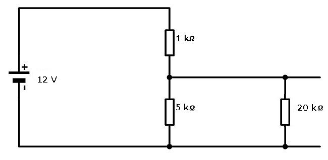
A load with a resistance of 20 kΩ is placed on the output of the 5 kΩ resistor. Let us first calculate the potential difference across the 5 kΩ resistor without a load. Then we will calculate the potential difference across the 5 kΩ resistor with the 20 kΩ load placed in the circuit.
Calculating the pd without a load added to the potential divider.
Calculatng the pd across the 5 kΩ resistor with a load having a resistance of 20 kΩ added across it.
We need to work out the overall resistance of the output branch of the circuit. This is composed of two resistors in parallel. To determine the overall resistance of this part of the circuit we must use the equation for adding resistors in parallel together.
We can now use this value in the potential divider equation. The resistance values are therefore 1 kΩ and 4 kΩ (which is lower than the 5 kΩ unloaded circuit)
As you can see, any time we add a component to a potential divider circuit that draws a current and has a resistance, the actual potential across the potential divider will be less than the theoretical maximum because of the overall reduction of the resistance in this part of the circuit.
Using the potential divider equation
Attempt to solve the question yourself before clicking the solve button!
Determining Resistance
Attempt to solve the question yourself before clicking the solve button!
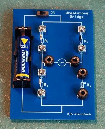
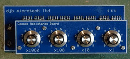
Wheatstone Bridge
A circuit can be setup with two pairs of resistors in parallel. The ratio of the resistances can be used for three known resistors to find the value of the fourth unknown resistance. This is often done with two fixed resistors, a decade board (which allows you to change the third resistor to a known value) and the unknown resistor. See the images below:
The circuit diagram for this is shown below:
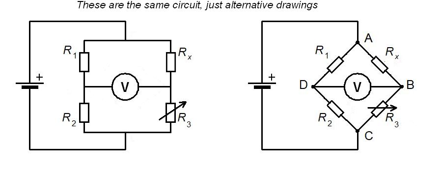
0 V will be regitstered on the voltmeter when the relationship between the resistors is balanced. (Note: you can also use an ammeter instead of a voltmeter because when balanced at 0V the current will also be 0 A) This occurs when the resistor ratio on the left branch is equal to the resistor ratio on the right branch. This is given in the equation:
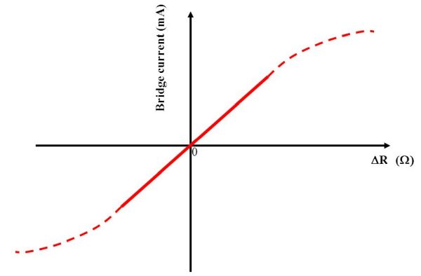
Note that R3 is the place for the decade resistance board to be connected. When the ratios are out by a small amount a graph can be plotted of voltage or current against resistance which will give a straight line.
Determining the Potential Difference across the Wheatstone Bridge
It is possible to calculate the potential difference acros the Wheatstone bridge if we use our knowledge of potential dividers. We can calculate the potential difference across both of the lower resistors, R2 and R3, on each side of the bridge. Subtracting one value from the other will give us the reading on the voltmeter. This is given in the following equation:
Calculations with mixed series and parallel circuits
In this section we will have a look at an examples used of a mixed circuit and how it can be answered. This work will require understanding that series circuits divide potential, and parallel circuits divide current. If you are not confident with these concepts then go over the material above to consolidate your understanding.
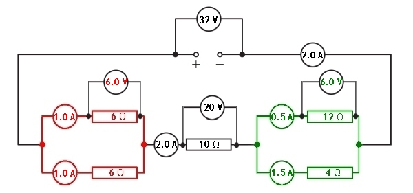
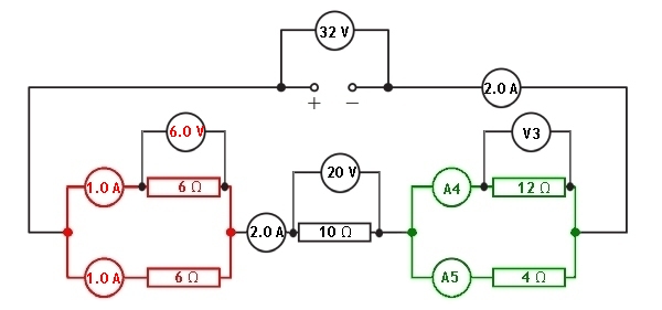
A mixed series and parallel circuit is setup and shown in the diagram below:
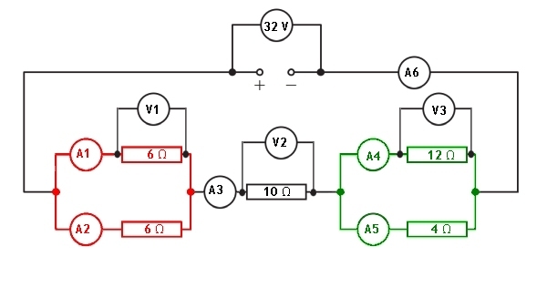
Let us look at the information given to us in the circuit diagram.
We have been given the values of each resistor and the supply potential difference. All of the ammeters in the circuit and the voltmeters across the components are blank. Let us now look at how we can calculate the missing values in each of the ammeters and voltmeters.
To be able to determine the total current passing through the supply we must know the total resistance of the circuit. We can then apply Vs = IRT to find the current passing through the supply, and all series parts of the circuit.
Red parallel section
The resistance in the circuit from this section can be calculated using:
The series resistor between the two parallel sections has a resistance of 10 Ω
Green parallel section
The resistance in the circuit from this section can be calculated using:
The total resistance of the circuit can now be calculated by adding the reistances of the two parallel sections to the series resistor.
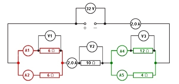
Having claculated that the total resistance of this combined circuit is 16 Ω we can now determine the current flowing through the supply.
Remember: Vs = IRT
We have now calculated the current in all series parts of the circuit. This gives us the value of the current in ammeters A3 and A6
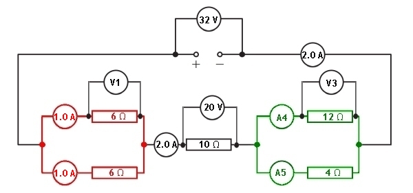
With the current through the series resistor now known, we can calculate the potential difference across the 10 Ω resistor using Ohm's Law.

We can now calculate the current in each of the branches of the parallel section coloured red
Looking at this part of the circuit we can see that the resistors in both branches of this section have the same value. This means that the current will be equally divided between the two branches. The series current is 2.0 A. When we divide this by 2 we can see that the current in each branch will be 1.0 A
With the current through the branches of the parallel resistors now known, we can calculate the potential difference across the 6 Ω resistors using Ohm's Law.
We can calculate the potential difference across the other parallel section of the circuit because the total potential difference across all sections of components must equal the supply voltage.
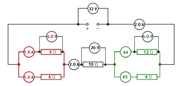
Knowing the potential difference across the green parallel section we can now find out the current flowing through each branch. This can be found using Ohm's Law.
For the reading on ammeter A4
For the reading on ammeter A5