Electrical Charge Carriers
Outer shell electrons are free to move in metals. This is what gives metals their ability to conduct electricity as solids. These delocalised electrons are moving randomly in the metal, with no overall flow of charge. The result is that the metal is electrically neutral with no charge transfer occuring. When a power supply or battery is attached to the metal it is possible to generate a current.
The current generated by applying an electric field from a power supply causes electrons to move through the circuit. The amount of current passing a point in a second is measured in Amperes. This is shortened to Amps and given the symbol (A). A picture of the movement of an electron through the metal would look like the diagram below:
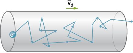
Notice that the overall velocity of the electron is to the right in this diagram. The actual path is complicated because of the number of collisions the electron has with other particles in the wire. The actual speed of the electron through the material is a fraction of a centimetre per second.
Electrical current is defined as the amount of charge transferred per unit time. In other words 1 Amp is equivalent to the passing of 1 Coulomb of charge accross a point in 1 second. This can be expressed in an equation as
Where Q = charge in Coulombs
I = current in amps
t = time in seconds
Example
When 5 Amps of current is measured in a circuit for 20 seconds. How much charge has passed the point?
Q = ?
I = 5 A
t = 20 s
Example
How long would it take to pass 3 C of charge using a current of 50 mA?
Q = 3 C
I = 50 mA = 50 × 10-3
t = ?
Determining the current used
Attempt to solve the question yourself before clicking the solve button!
Direct Current
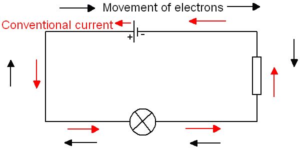
This is a current which flows round a circuit in a single direction. Cells, batteries and d.c. power supplies provide this type of current. Direct current (d.c.) in conventional terms always flows from positive to negative. In the diagram below we can see conventional current travelling around the circuit in an anti-clockwise direction. The actual charge carriers are the electrons and they travel in a clockwise direction around the circuit.
Conventional Current
Before the discovery of electrons scientists thought that electric current was the consequence of the movement of positive charge. With the discovery of the electron and atomic structure we now know that current occurs because of the movement of electrons. In physics the concept of current is still based on the movement of positive charge, and is called conventional current. When you see a current arrow on a diagram that refers to conventional current you will see that it goes from the positive terminal of the power supply to the negative one. The convention is so settled that it will not change and so students of National 5 physics must take this into consideration when thinking about current. The arrows for conventional current point in the opposite direction to the movement of the electrons.
Alternating Current
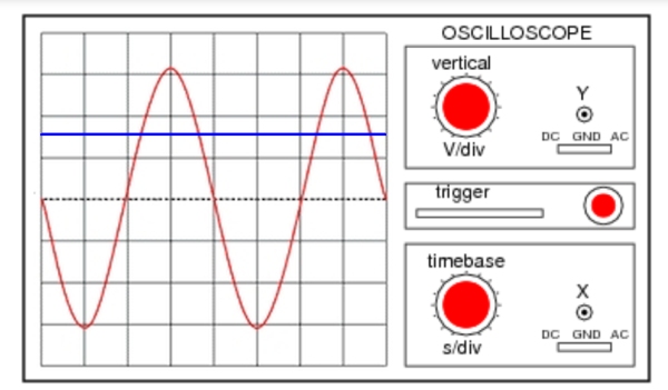
When using mains electricity at home the type of current is known as alternating current (a.c.) This current reverses direction many tmes per second. In the UK and Europe this is with a frequency of 50 Hz and in North America it is 60 Hz. It is possible to identify whether or not the electrical supply is alternating or direct by using an oscilloscope. A data logger could be used instead of an oscilloscope to show either a.c. or d.c. current. Below is a diagram where the red trace is the a.c. signal and the blue trace is the d.c. signal.
Example
The timebase for an oscilloscope is set at 2 ms/div. On the screen a single a.c. wave takes 10 divisions
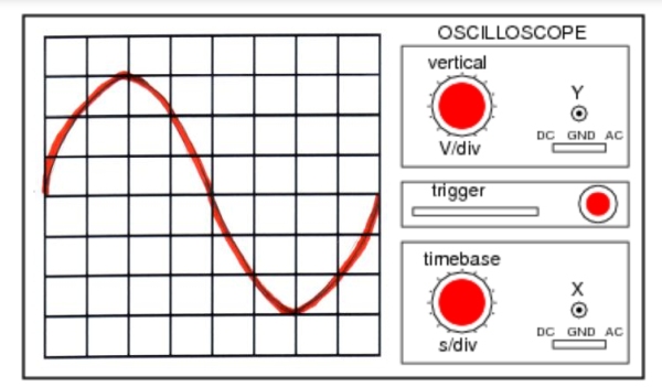
This means that the a.c. sine wave takes 10 × 2 ms = 20 ms to pass across the screen. This time is the period (T) of the wave. We can calculate the frequency of the wave using
The frequency of the a.c. electrical supply is therefore 50 Hz.
Below is a link to summary notes and some multiple choice questions
Electric Charge Carrier Revision Notes - pdf