Practical electrical and electronic circuits
Measuring Current, Potential Difference and Resistance
The placing of meters in the circuit depends upon what you want to measure.
Current - An ammeter is placed in series in the circuit where you wish to measure the current
Potential Difference (Voltage) - A voltmeter connected on either side of the component, in parallel, that you wish to measure the potential difference across.
Resistance - An ohmmeter connected on either side of the component that you wish to measure the resistance of.
The measurement of potential difference always occurs between two points, where the voltmeter is attached to the circuit. Remember the voltmeter is always connected to the circuit in parallel to the part of the circuit where the reading is being taken. In the graphic below the voltmeter is connected to different parts of the circuit and the potential difference between the two points is measured. The voltage in the external circuit cannot be greater than the supply voltage unless another power source is added to the circuit.
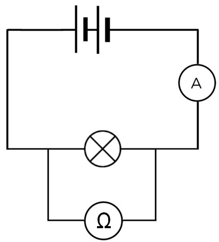
The diagram below shows an arrangement of a simple series circuit with one lamp in it, and where to place the meters to measure current and potential difference.

If you wished to measure the resistance of the lamp the voltmeter would be swapped with an ohmmeter shown in the circuit below
.
Below is a labelling activity to help consolidate your understanding of where the components in a series circuit go in order to meaure the current through the resistor and the potential difference across the resistor.
When looking at circuits with more than one component in series the placement of the meters to measure current are shown below in the diagram.
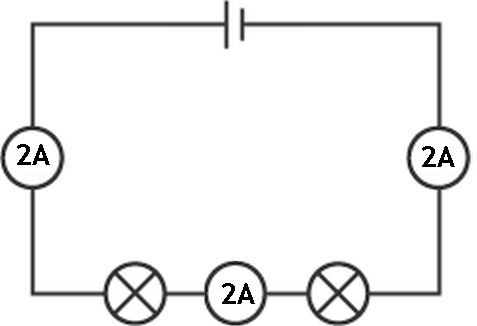
From the diagram above we can see that the current is the same at all points in a series circuit. This is true for all series circuits.
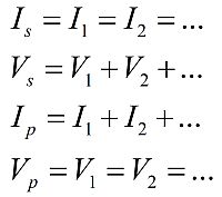
This can be expressed mathematically as Is = I1 = I2 = ...
When measuring the potential difference across two lamps in series the diagram below shows how this can be achieved.
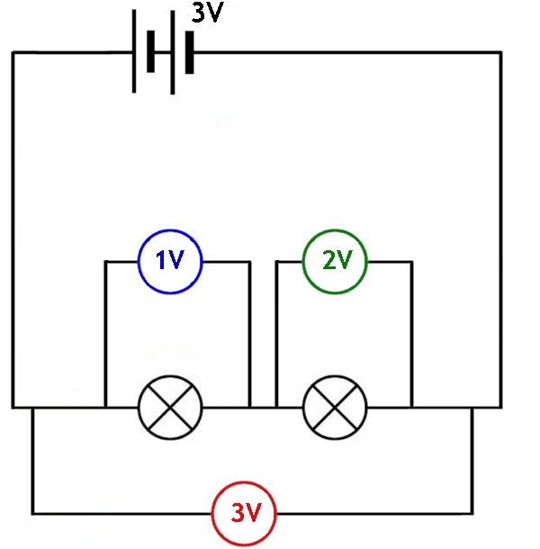
As you can see in the diagram it is possible to determine the potential difference for each lamp individually (left lamp voltmeter = 1 V and right lamp voltmeter = 2 V) as well as the total potential difference across both lamps, (the red voltmeter shows the potential difference across both lamps = 3 V)
This can be expressed mathematically as Vs = V1 + V2 + ...
From this we can conclude that in series circuits the current remains the same at all points in the circuit and the voltage is split across the different components in the circuit. This is why two components in series are known as a potential divider circuit. We will come across potential dividers when looking at Ohm's Law and using transistors/MOSFETs as switches.
Let us now look at where ammeters would be placed in a parallel circuit to measure the current.
Remember that a parallel circuit is one in which there is more than one path for the current to flow through. Each different path is called a branch.
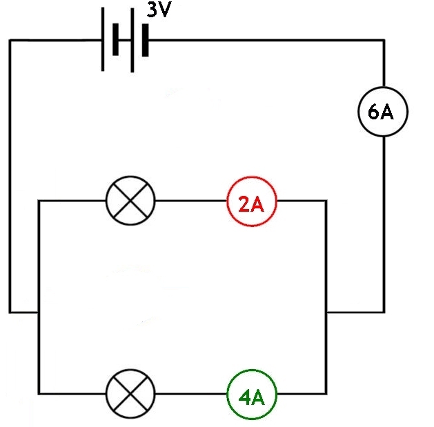
You can see from the diagram that the total current can be measured in the wire the comes from the power supply. In this case it is a 3 V battery. The total current is measured as 6A. In the parallel section of the circuit we can see that the current has been split into two parts. The current in the top part of the parallel section is shown with the ammeter coloured in red = 2A. In the lower part of the parallel section we can see the ammeter coloured in green = 4A. We can also see that the total current in the two branches is the same as the total current flowing through the supply. (2A + 4A = 6A)
This is an important principle in parallel circuits. The total current arriving at a junction must be the same as the sum of all the currents in the brances at that junction.
This can be expressed mathematically as Ip = I1 + I2 + ...
In the diagram below you can see where the voltmeters must be placed when measuring the potential difference across two lamps connected in a parallel circuit.
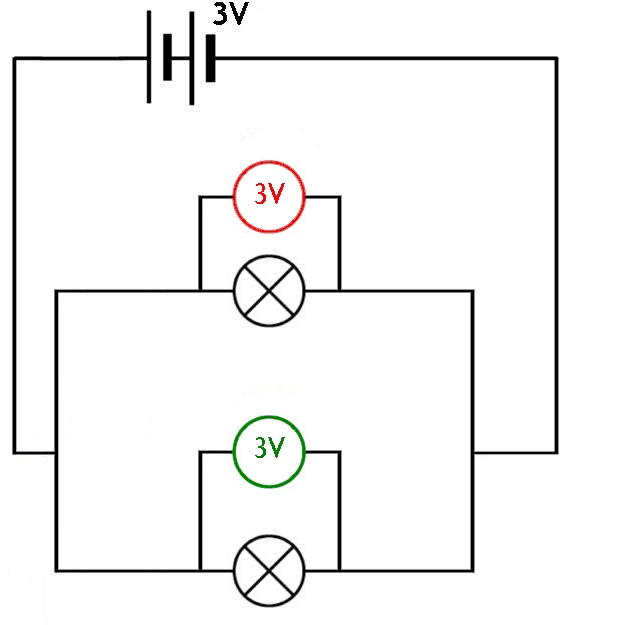
We can see in this circuit the potential difference is the same across both branches of the parallel circuit. This will always be the case across all the branches in a section of a circuit that is parallel.
This can be expressed mathematically as Vp = V1 = V2 = ...
For a parallel section in a circuit we can therefore conclude that the current is split, but the potential difference remains the same in the different branches.
Current in Series and Parallel Circuits
Series Circuit
A series circuit is one that is has all of the components in a single loop. In these circuits the current is the same at all points in the circuit. Looking at the diagram below you can see that each ammeter records the same value. It does not matter where in the circuit the ammeter is put. The current rule for a series circuits is that the current is the same at all points in the circuit.
Parallel Circuit
Below is an example parallel circuit with 2 lamps. The circuit also contains ammeters to show how the current flows through different parts of the circuit.
In the circuit above you can see that the total current is 6 amps. This current is then split across the two lamps that are parallel to each other. In one branch the current is 2 amps. The other branch must have a current of 4 amps. The total current from the supply must be equivalent to the sum of the currents in both parts of the parallel circuit.
From the two examples above we can see that the current is the same at all points in the series circuit and that the current is divided by the parallel circuit.
Potential Difference in Series and Parallel circuits
Series Circuit
From the diagram above we can see that the supply voltage is 3 V. The total potential difference across both lamps must also equal 3 V.
This is shown by the red voltmeter in the diagram. This voltmeter shows the total potential difference across both lamps.
To measure the potential difference across a single lamp we must place the voltmeter so that it only includes the lamp that we wish to measure. For the left hand lamp, the voltmeter shows that it has a potential difference of 1 V across it.
This is shown by the blue voltmeter in the diagram. This voltmeter shows the potential difference across the left hand lamp.
The right hand lamp also has a voltmeter across it, and this shows a reading of 2 V. This tells us that the potential difference across the right hand lamp is 2 V.
This is shown by the green voltmeter in the diagram. This voltmeter shows the potential difference across the right hand lamp.
From this circuit you can see the total energy supplied by the source was used up by the components in the circuit. This will always happen. You can also see that one lamp uses more energy than the other because they have different potential differences across them.
Parallel Circuit
From the diagram above you can see that the potential difference in each branch of the parallel part of the circuit is the same as the supply voltage. All the branches of a parallel circuit section have equal potential differences. If there is only one parallel section then the potential difference across each of the branches will be the same as the voltage of the supply.
From the two examples above we can see that the voltage is divided by a series circuit and that it is the same in all branches of the parallel circuit.
More complex mixed series and parallel circuits.
Look at the diagram below and you will see that there are two separate parallel sections with a series resistor inbetween them. We will look at how to measure the potential diference and the current at various points in the circuit.
Measuring current

In the diagram above we can see that the current passing through the supply is 10A. At all series parts of the circuit this will be the current passing through the components that are in series with the power supply.
The left hand parallel section shows that the current splits into 8A through the top resistor, and 2A through the bottom resistor. Note that these two currents add to give 10A. Current cannot be lost when parallel branching occurs. This means that both currents at the split must add up to give the same current as passes through the power supply.
The right hand parallel section shows that the current splits into 6A through the top resistor, and 4A through the bottom resistor. Note that these two currents add to give 10A. Current cannot be lost when parallel branching occurs. This means that both currents at the split must add up to give the same current as passes through the power supply.
Measuring potential difference
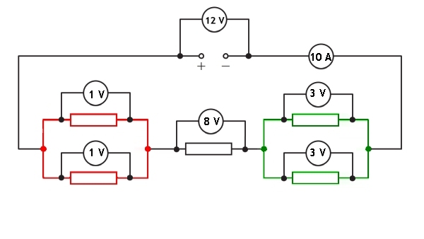
You can see that the potential difference across the left hand parallel section is 1 V, the potential difference across the serial resistor is 8 V and the potential difference across the right hand parallel section is 3 V.
When we add these three values together we get 1 + 8 + 3 = 12 V. This is the same as the voltage provided by the power supply. Remember that we only need to know the voltage across one branch of the parallel section in order to add it to any series components and therefore calculate the total voltage across the components in the circuit.
Measuring current
You can see that the current flowing through the supply is 10 A. When the current gets to the left hand parallel resistors section it is split into an 8 A current flow in the top branch and a 2 A current flow in the bottom branch. As the current passes through the series resistor in the middle, it is a current of 10A. When the current gets to the right hand parallel resistors section it is split into a 6 A current flow in the top branch and a 4 A current flow in the bottom branch.
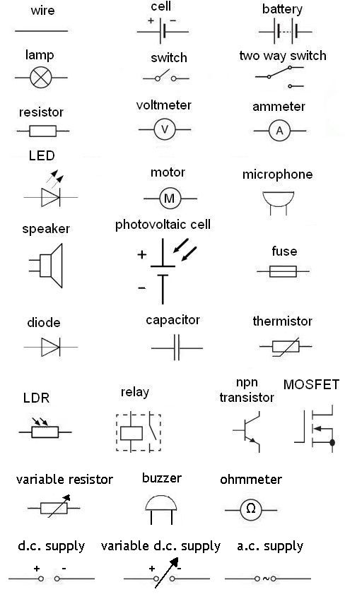
Identifying Component Symbols
The image below shows all of the common electrical components that you are likely to come across in N5 physics. Below the diagram is an activity that will allow you to test how well you know what each of the symbols represents.
Components and their uses
| Component | Function and Application |
|---|---|
| cell | a source of potential difference in a circuit, produicing a d.c. current. |
| battery | two or more cells in series, a battery provides a higher potential difference than a cell. |
| lamp | a component that converts electical energy into light energy. |
| switch | a component that can cause a break in a circuit when open. |
| resistor | a component that converts electrical energy into heat energy. |
| voltmeter | a component that is used to measure the potential difference across another component in a circuit. It must be placed in parallel to the component which is being measured. |
| ammeter | a component that is used to measure the current flowing through a part of a circuit. It mus always be placed in series in the circuit. |
| LED | a diode that converts electrical energy into light. These are much more efficient than filament lamps. |
| motor | a component that converts electrical energy into kinetic energy, often rotational. |
| microphone | a component that converts sound energy into electrical energy. |
| loudspeaker | a component that converts electrical energy into sound energy. |
| photovoltaic cell | a component that converts light energy directly into electrical energy. |
| fuse | a component that will break if the current from the supply is too high. This saves the cable that attaches to the power supply from becoming to hot and causing a fire. |
| diode | a component that allows electric current to flow in only one direction. |
| capacitor | a component used in timing circuits because it takes time to charge and to discharge. |
| thermistor | a component that has a lower resistance when it is heated. |
| LDR | a component that has a lower resistance when light shines upon it. |
| relay | a component that allows a small current and voltage in a separate circuit to turn on a much higher current and voltage in a secondary circuit. |
| transistor | a component that is used as a switch with no moving parts. It can switch on and off very quickly and is found in computer chips and control systems. |
npn transistor
At national 5 level the use of the npn transistor is as an electroncic switch. It is paired with a potential divider circuit. The potential divider circuit often has a component which will respond to a change in the surroundings, such as a thermistor, LDR or capacitor. These transistors only work at low voltages and should not be attached directly to mains powered circuits.
The symbol for an npn transistor is given below.
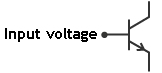
Notice that one of the three connections is labelled as input voltage. It is important to know that an npn transistor will only switch on if the input voltage is above 0.7 V
Below is an example of a transistor in a light controlled circuit.
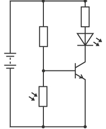
In the above circuit the light dependent resistor (LDR) will change in resistance with the amount of light on it.
In the dark
In the dark it will have a very high resistance. We have learnt that the voltage across a component with a high resistance will also be high. In this circuit when it is dark the voltage across the LDR will also be high. This means that the input voltage for the transistor will be high as well. The transistor will be switched on. This means that the LED will be lit.
In the light
When the LDR is in the light it will have a low resistance. Components with low resistance require only a low voltage across them. The low voltage across the LDR will be less than the 0.7 V required to switch on the transistor. This means that in the light the transistor will be switched off. This means that the LED will be off.
MOSFET
A MOSFET behaves in a very similar way to the npn transistor. It is also used as an electrical switch. The circuit symbol is below
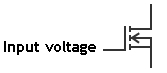
Notice that one of the three connections is labelled as input voltage. It is important to know that a MOSFET will only switch on if the input voltage is above 2.0 V
An example circuit is shown below
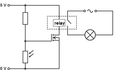
In this circuit the light dependent resistor (LDR) will have a high resistance when in the dark. This means that a voltage of more than 2.0 V will be measured across the LDR. This results in the MOSFET input voltage being greater than 2.0 V. When the input voltage is more than 2.0 V the MOSFET will be switched on. This will swith on the relay which switches on the external light. Therefore this circuit could be used to switch on lights when it starts to get darker.
When light shines on the LDR it will have a low resistance. This means that a voltage of less than 2.0 V will be measured across the LDR. This results in the MOSFET input voltage being less than 2.0 V. When the input voltage is less than 2.0 V the MOSFET will be switched off and the relay will not switch on the external light.
Resistance
Resistance is a measure of how much opposition there is to the flow of current in a component. If the component has a high resistance it will require a lot of energy to push electrons through it. This means that it would take a larger amount of the potential difference supplied by the power source than another component with a smaller resistance.
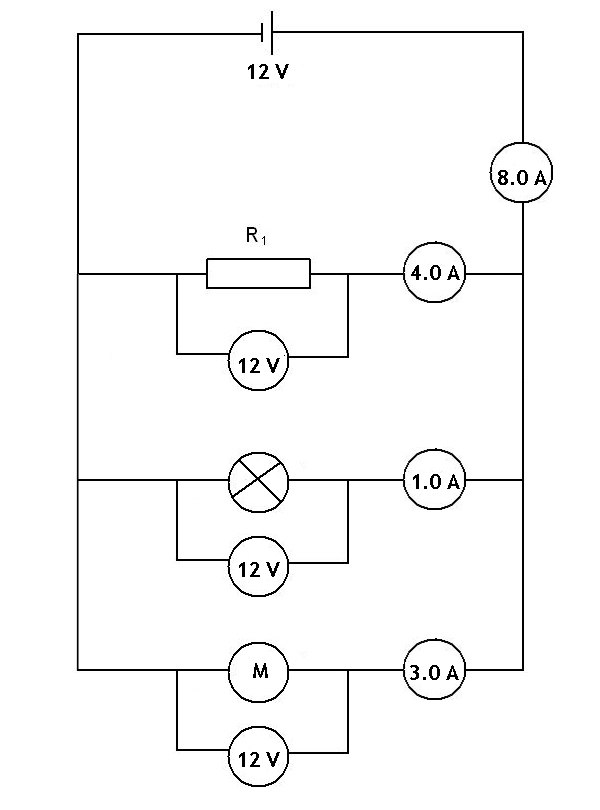
We can use our knowledge of Ohm's Law (V = IR) to calculate the value of each resistor in the circuit illustrated below.
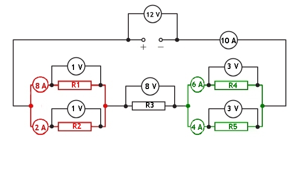
V = IR1, where V = 1 V, I = 8 A, so R1 = 1/8 = 0.125 Ω
V = IR2, where V = 1 V, I = 2 A, so R2 = 1/2 = 0.50 Ω
V = IR3, where V = 8 V, I = 10 A, so R3 = 8/10 = 0.80 Ω
V = IR4, where V = 3 V, I = 6 A, so R4 = 3/6 = 0.5 Ω
V = IR5, where V = 3V, I = 4 A, so R5 = 3/4 = 0.75 Ω
Resistors in Series
When we have two components in series they will both have the same current flowing through them, but they may have different protential differences across them. In the example below there is a resistor and a lamp. The current in the circuit is shown on the ammeter as 5.0 A. The voltage across the resistor is 4.0 V and the voltage across the lamp is 2.0 V.
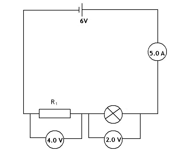
What is different about the two components? Why does it take 4.0 V of energy to push the current of 5.0 A through the resistor, but only 2.0 V of energy to push the same current through the lamp?
The reason for the difference is that the resistor has a greater resistance than the resistance of the lamp.
We can calculate the resistance of these two components using Ohm's Law, V = IR
Resistor
V = IR1
4.0 = 5.0 × R1
R1 = 0.8 Ω
Lamp
V = IRlamp
2.0 = 5.0 × Rlamp
Rlamp = 0.4 Ω
This shows us that a component with a lower resistance (the lamp) requires less potential difference to push the current through the component.
You can also see that a component with twice the resistance of the other component will require twice the potential difference to keep the current flowing.
Adding another resistor in series
What would happen to the potential difference across the resistor and lamp if another component was added. Let us look at the circuit above and what happens to the voltages across each component when a motor with a resistance of 1.2 Ω is added to the circuit in series. This new circuit is shown below.
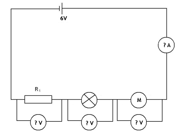
We can calculate the total resistance in the circuit by adding the resistances of the three components together. This is because when working with a series circuit the resistances add as shown in the equation below:
In the circuit above:
R1 is the resistor with a resistance of 0.80 Ω
R2 is from the lamp with a resistance of 0.40 Ω
R3 is from the motor with a resistance of 1.20 Ω
Finding the total resistance comes from substituting all these values into:
Substituting gives
We can now use Ohm's law to calculate the current in the circuit because we know that the current is the same at all points in the circuit. We also know the pd from the battery and the total resistance in the circuit.
We can see that adding another component with resistance into the circuit we have reduced the current flowing through the circuit. With two components there was a current of 5.0 A, but in the circuit with the tree componnents and the same supply, the resistance in the circuit has increased. In the three component circuit there is now only a current of 2.5 A flowing through the circuit.
What happens to the potential differences across each component?
Now that we know the current we can use Ohm's law across each individual compenent to determine the potential difference across each one.
Resistor 1
Lamp
Motor
We can check that the potential differences across all three components add to give the supply voltage.
We can see that the potential differences across the three components add to give the same as the supply voltage.
We can also see that the potential differences across the resistor and lamp are lower when the motor has beed added.
From this we can see that adding another component in series to a series circuit causes the current in the circuit to be reduced, as well as reducing the potential difference across all the components.
Resistors in Parallel
When we have two resistors in parallel they will both have the same potential difference across them, but they may have different currents through them. In the example below there is a resistor and a lamp. The current at different points in the circuit is shown, as well as the potential difference across the components. In the circuit below there is a resistor with a current of 4.0 A and a lamp in a separate branch with a resistance of 1.0 A. The total current in the circuit is 5.0 A, and the potential difference across the two components is the same as the supply voltage, 12 V.
The resistance of both components can be calculated using Ohm's Law, V = IR
Resistor
V = IR1
12 = 4.0 × R1
R1 = 3.0 Ω
Lamp
V = IRlamp
12 = 1.0 × Rlamp
Rlamp = 12 Ω
We can see that the current is lower in the branch with the component that has the highest resistance. Here the lamp has 4 times the resistance of the resistor, and the lamp's current is reduced to a quarter of the current through the resistor.
To calculate the total resistance of this circuit we much use:
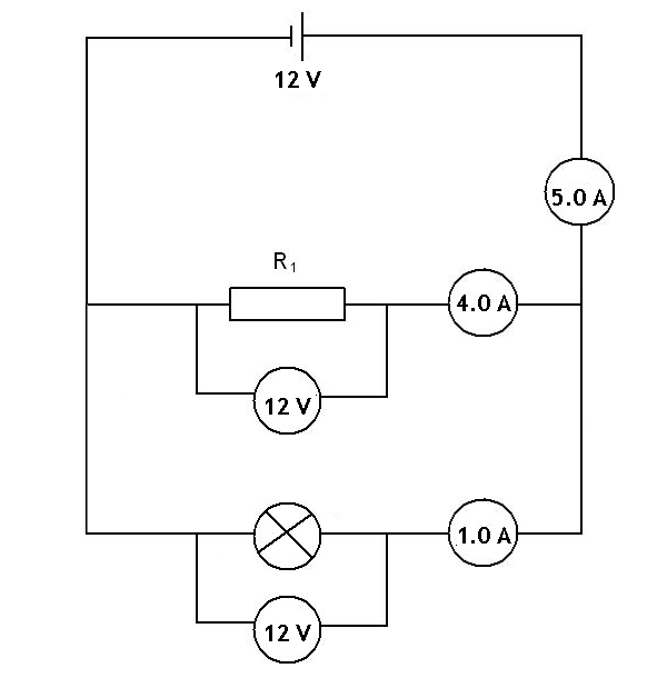
Adding another resistor in parallel
What would happen to the potential difference across the objects in parallel, and what would happen to the current through them? A motor with a resistance of 4 Ω is added to the circuit in parallel to the other components. What will happen to the current and potential difference across the components in this new circuit? This new circuit is shown below.
We can calculate the total resistance in the circuit by adding the resistances of the three components together. This is because when working with a parallel circuit the resistances add as shown in the equation below:
Substituting gives
From this we can see that the total resistance of the circuit has been reduced. The result is that a greater current flows through the power supply, and the additional current flows through the newly added branch. Notice that the current and potential differences for the two components that were already in the parallel circuit have not changed.
We have added a new branch for current to flow through and so more current is drawn from the power supply. As the example above shows.
Calculations with mixed series and parallel circuits
In this section we will have a look at an examples used of a mixed circuit and how it can be answered. This work will require understanding that series circuits divide potential, and parallel circuits divide current. If you are not confident with these concepts then go over the material above to consolidate your understanding.
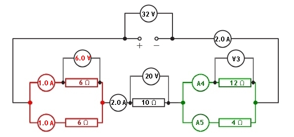
A mixed series and parallel circuit is setup and shown in the diagram below:
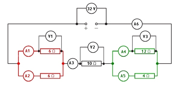
Let us look at the information given to us in the circuit diagram.
We have been given the values of each resistor and the supply potential difference. All of the ammeters in the circuit and the voltmeters across the components are blank. Let us now look at how we can calculate the missing values in each of the ammeters and voltmeters.
To be able to determine the total current passing through the supply we must know the total resistance of the circuit. We can then apply Vs = IRT to find the current passing through the supply, and all series parts of the circuit.
Red parallel section
The resistance in the circuit from this section can be calculated using:
The series resistor between the two parallel sections has a resistance of 10 Ω
Green parallel section
The resistance in the circuit from this section can be calculated using:
The total resistance of the circuit can now be calculated by adding the reistances of the two parallel sections to the series resistor.
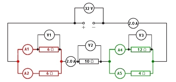
Having claculated that the total resistance of this combined circuit is 16 Ω we can now determine the current flowing through the supply.
Remember: Vs = IRT
We have now calculated the current in all series parts of the circuit. This gives us the value of the current in ammeters A3 and A6
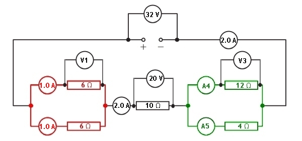
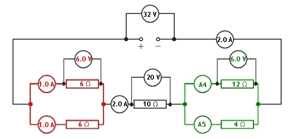
With the current through the series resistor now known, we can calculate the potential difference across the 10 Ω resistor using Ohm's Law.

We can now calculate the current in each of the branches of the parallel section coloured red
Looking at this part of the circuit we can see that the resistors in both branches of this section have the same value. This means that the current will be equally divided between the two branches. The series current is 2.0 A. When we divide this by 2 we can see that the current in each branch will be 1.0 A
With the current through the branches of the parallel resistors now known, we can calculate the potential difference across the 6 Ω resistors using Ohm's Law.
We can calculate the potential difference across the other parallel section of the circuit because the total potential difference across all sections of components must equal the supply voltage.
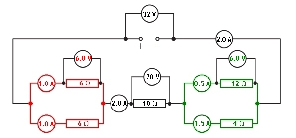
Knowing the potential difference across the green parallel section we can now find out the current flowing through each branch. This can be found using Ohm's Law.
For the reading on ammeter A4
For the reading on ammeter A5
More information will appear here as the website develops.