Ohm's Law
Georg Ohm a German scientist experimentally determined the relationship between potential difference (in V) and current (in A) for a variety of conducting materials. He found that for certain materials there was a linear relationship given by the relationship:
Where:
V is the potential difference (V)
I is the current (A)
R is the resistance (Ω)
Materials obeying this linear relationship are said to obey Ohm's Law. Ohm's Law can be stated as "the current through a conductor between two points is directly proportional to the voltage across the two points". Notice that direct proportionality means that the straight line will pass through the origin (0, 0).
It is possible to see a graph with this information Assignment - Ohmic conductor.
Consider the following graph of current vs voltage.
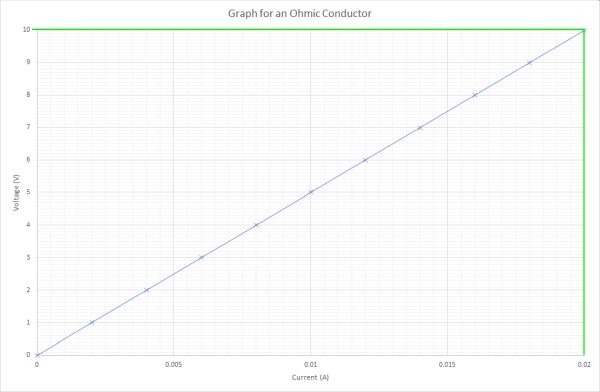
Using the points (0, 0) and (0.02, 10), as marked on the graph, we can determine the gradient of the line. The gradient of the line is equivalent to the value of the ohmic conductor. Therefore calculating the gradient of the line will let us find out the value of the resistance of the ohmic conductor.
The ohmic conductor has a resistance value of 500 Ω
Example 1
A series circuit has a resistor and a power sypply. The power supply gives 12 V to the circuit and the current is measured as 2 amps. What is the resistance of this circuit?
Information from question:
V = 12 V
I = 2 A
R = ? Ω
The Potential Divider Equation
When we have a simple circuit with two resistors in series it is possible to work out how much energy each resistor takes from the power supply. Consider the following circuit:
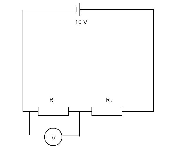
If resistors R1 and R2 are identical the voltage across each resistor will be 5 V. Consider the case when R1 and R2 are both 50 Ohms. The total resistance in the circuit will be given by:
With the total resistance in the circuit known we can work out the current in the circuit.
V = 10 V
I = ? A
R = 100 Ω
Knowing the current is the same at all points in a series circuit allows us to calculate the voltage passing through each resistor
As was predicted earlier, identical resistors will each take half of the supply voltage. Here we see that the supply voltage of 10 V was split into 5 V across each resistor.
What about when the two resistors are not identical. In this case we have to use the potential divider equation:
Where:
V2 is the voltage across resistor 2
R1 and R2 are the resistances for resistors 1 and 2 respectively
Vs is the supply voltage
Example
Consider a potential divider system where the supply voltage is 12V. The two resistors have resistances of 4 Ω and 8 Ω. What is the current in the circuit and what is the voltage across each of the resistors.
To calculate the current we must first remember to calculate the total resistance:
With the total resistance it is possible to calculate the current in the circuit:
Now that we have the current we need to calculate the voltage over each resistor. This is possible using V = IR
The voltage over the second resistor is straight forward because Vs = V1 + V2
V2 = 12 - 4 = 8 V
There is an alternative method for working out the voltage, especially if you are not asked for the current. This involves using the potential divider equation mentioned earlier.
V2 = ?
R1 = 4 Ω
R2 = 8 Ω
Vs = 12 V
Interactive determining the potential difference across R2 with solution
Attempt to solve the question yourself before clicking the solve button!
Interactive determination of the resistance of R2 with solution
Attempt to solve the question yourself before clicking the solve button!
Resistors in Series or V1/V2 = R1/R2
In a series circuit the current is the same in all components. This means that a simple relationship can be expressed showing the relationship between the ratios of the potential differences across each of the resistors. This is given by:
If we know the potential difference across one resistor it is possible to determine the other potential difference by using the known value of both resistors.
What potential difference would there be across a resistor of 50 Ω when the other resistor with a resistance of 10 Ω in series has a potential drop of 8.0 V. We can use the relationship given above to find the answer. Let us state that V1 is the unknown potential difference. This makes R1 = 50 Ω, V2 = 8.0 V, and R2 = 10 Ω.
Substitute in the values to get:
As you can see above the choice of V1 as the unknown makes the calculation straightforward.
One way of simplifying the calculation is to make sure that the unknown piece of information, either potential difference or resistance is on the top line of the fraction. This means setting either V1 or R1 as the unknown peice of information and then filling in the other values that are given.
Determining an unknown resistance from two resistors in series
Attempt to solve the question yourself before clicking the solve button!
Temperature and resistance in conductors
In most conductors when the temperature of the material increases, so does the resistance to current flow. Why does resistance increase in most substances when the temperature increases?
When electrons flow through a material they experience resistance. In the section on Electrical Charge Carriers we were introduce to the idea that the flow of electrons through a wire is affected by random collisions. This is shown in the diagram below for a single electron:
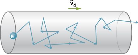
When the wire is heated the particles in the wire vibrate more. These increased vibrations cause the electron to be bounced about more. This makes it more difficult for the electron to pass through the wire. Therefore the resistance of the wire increases when it is heated.
An exception to this rule of increasing resistance with increased temperature is the thermistor. The thermistor is a device where the resistance decreases when the temperature is increased. This is a very unusual, but useful behaviour. The symbol for a thermistor in electrical circuits is shown below:

An example of the change in resistance when something is hot is when you switch on an electric kettle. The resistance of the heating element at room temperature is 30 Ω. When the element has heated the water to boiling the resistance of the heating element is 35 Ω. The hot heating element has a higher resistance than when it is cold.
Experiment verifying Ohm's Law
Ohm's law states that the the current between two points is directly proportional to the potnetial difference (voltage) across the two points. The equation used to show this relationship is:
To carry out an experiment to verify this law a variable voltage power supply, resistor, ammeter and voltmeter are required. The circuit diagram is given below:
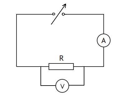
The variable voltage power supply is set at 1.0 V. Both the current and voltage are recorded. The power supply is then increased in 1.0 V steps, with the current and voltage being recorded each time. A graph of voltage (y-axis) versus current (x-axis) is then plotted. A component that obeys Ohm's law will result in a straight line of best fit that foes through the origin.
Some example results are given below
Voltage and current results for a resistor of unknown resistance
| Current (A) | Voltage (V) |
|---|---|
| 0.005 | 1.0 |
| 0.010 | 2.0 |
| 0.015 | 3.0 |
| 0.020 | 4.0 |
| 0.025 | 5.0 |
| 0.031 | 6.0 |
| 0.035 | 7.0 |
| 0.040 | 8.0 |
| 0.044 | 9.0 |
| 0.050 | 10.0 |
The graph of these results is plotted below:
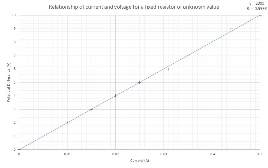
The gradient of this graph is equivalent to the value of the resistor. This hase been calculated as 200 Ω for the above set of results.